
In this article
Automotive interfaces
Automotive Ethernet and GMSL in LV124 / LV148 testing.
The bandwidth revolution in vehicles
Over the past decade, in-vehicle communication has undergone a fundamental shift. The traditional CAN bus — reliable, proven, but limited to 1 Mbit/s — can no longer carry the data volumes required by modern vehicle systems. ADAS cameras generate gigabits per second. Lidar sensors produce dense point clouds. Displays require high-resolution video feeds. Zonal architectures need high-throughput backbones connecting domain controllers.
Two interface technologies have emerged to meet this demand: Automotive Ethernet (100base-T1 and 1000base-T1) for general high-speed data transport, and GMSL (Gigabit Multimedia Serial Link) for point-to-point camera and display connections. Both are now standard in new vehicle platforms — and both create new challenges for LV124 / LV148 testing that did not exist five years ago.
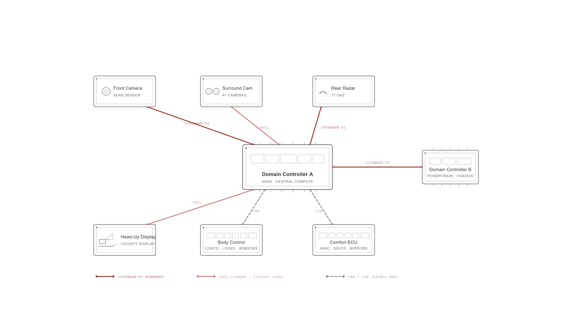
Three interface families — and what each carries
CAN / LIN
Legacy buses
The established workhorses. CAN runs at up to 5 Mbit/s (CAN FD), LIN at 20 kbit/s. Still used for body control, comfort, and low-bandwidth sensor networks. Not going away — but moving to a secondary role.
- Bandwidth: CAN 1 Mbit/s (classic), 5 Mbit/s (FD) · LIN 20 kbit/s
- Topology: Shared bus, multi-node
- Physical layer: Differential pair (CAN) · Single wire (LIN)
- LV124 test: Interruption on bus lines during all tests
Automotive Ethernet
High-speed backbone
The new backbone. 100base-T1 for sensor and control networks, 1000base-T1 for high-throughput applications like ADAS data fusion and gateway-to-gateway links. Single unshielded twisted pair — designed for automotive environments.
- Bandwidth: 100 Mbit/s (100base-T1) · 1 Gbit/s (1000base-T1)
- Topology: Point-to-point, switched
- Physical layer: Single unshielded twisted pair (1 pair vs. 4 in standard Ethernet)
- LV124 test: Interruption testing on Ethernet lines — critical
GMSL
Camera & display link
Gigabit Multimedia Serial Link — a high-bandwidth, low-latency point-to-point interface designed specifically for camera-to-ECU and ECU-to-display connections. Maxim/Analog Devices technology, increasingly used alongside Ethernet.
- Bandwidth: 3–6 Gbit/s (GMSL2) · up to 12 Gbit/s (GMSL3)
- Topology: Point-to-point, serialiser/deserialiser (SerDes)
- Physical layer: Coaxial cable or shielded twisted pair
- LV124 test: Interruption testing on GMSL lines — critical
The trend
Modern vehicles are moving toward fewer, more powerful ECUs connected by high-bandwidth interfaces — Ethernet for data transport, GMSL for camera/display, and CAN/LIN for legacy functions. Testing these new units under real-world electrical stress requires systems that can handle both high currents and high-speed interfaces — synchronised, automated, and reliable.
Why do high-speed interfaces need interruption testing?
LV124 and LV148 require short interruption tests on all ECU connections — including communication lines. This means that during electrical stress testing, the Ethernet and GMSL connections must be briefly interrupted and then restored, while monitoring whether the ECU maintains communication, recovers correctly, and does not enter an undefined state.
This requirement exists because real vehicles experience exactly these conditions. A connector that briefly loses contact due to vibration, a wiring harness with a marginal solder joint, or a pin that corrodes over time — all produce short interruptions on the communication line. If the ECU cannot handle a sub-millisecond interruption on its Ethernet connection without crashing, rebooting, or losing its camera feed, that is a safety-critical failure in an ADAS system.
Safety implication
An ADAS camera ECU that loses its Ethernet link for 100 microseconds due to a short interruption — and takes 2 seconds to re-establish the connection — has a 2-second blind spot. At highway speed, that is 60 metres of driving without camera input. This is why interruption testing on high-speed interfaces is not optional.
What actually happens during a short interruption on Ethernet?
A short interruption test on an Automotive Ethernet 1000base-T1 line is fundamentally different from the same test on a CAN bus — and the difference creates the testing challenge.
CAN is a robust, low-speed protocol designed for exactly these conditions. A short interruption on a CAN line typically results in a few lost frames — and the protocol recovers automatically within milliseconds. The ECU barely notices.
Ethernet is different. 1000base-T1 maintains a continuous physical-layer link with ongoing auto-negotiation, clock recovery, and frame synchronisation. When the link is interrupted — even for microseconds — the physical layer must re-establish the connection from scratch. This involves link training, auto-negotiation, and synchronisation, which can take hundreds of milliseconds to seconds depending on the PHY implementation.
During this recovery time, no data flows. For an ADAS system, this means no camera images, no lidar data, no radar returns — a complete sensor blackout.
GMSL behaves similarly. The serialiser/deserialiser link requires lock acquisition after an interruption, and the recovery time depends on the GMSL generation, the cable length, and the specific chipset implementation.
| Interface | Interruption tolerance | Typical recovery time | Impact |
|---|---|---|---|
| CAN | Robust — handles well | Milliseconds (protocol-level retransmit) | A few lost frames, auto-recovery |
| 100base-T1 | Moderate | 100–500ms | Link re-establishment required |
| 1000base-T1 | Sensitive | 200ms – 2s | Full link training, potential data loss |
| GMSL | Sensitive | 100ms – 1s | Lock re-acquisition, video freeze |
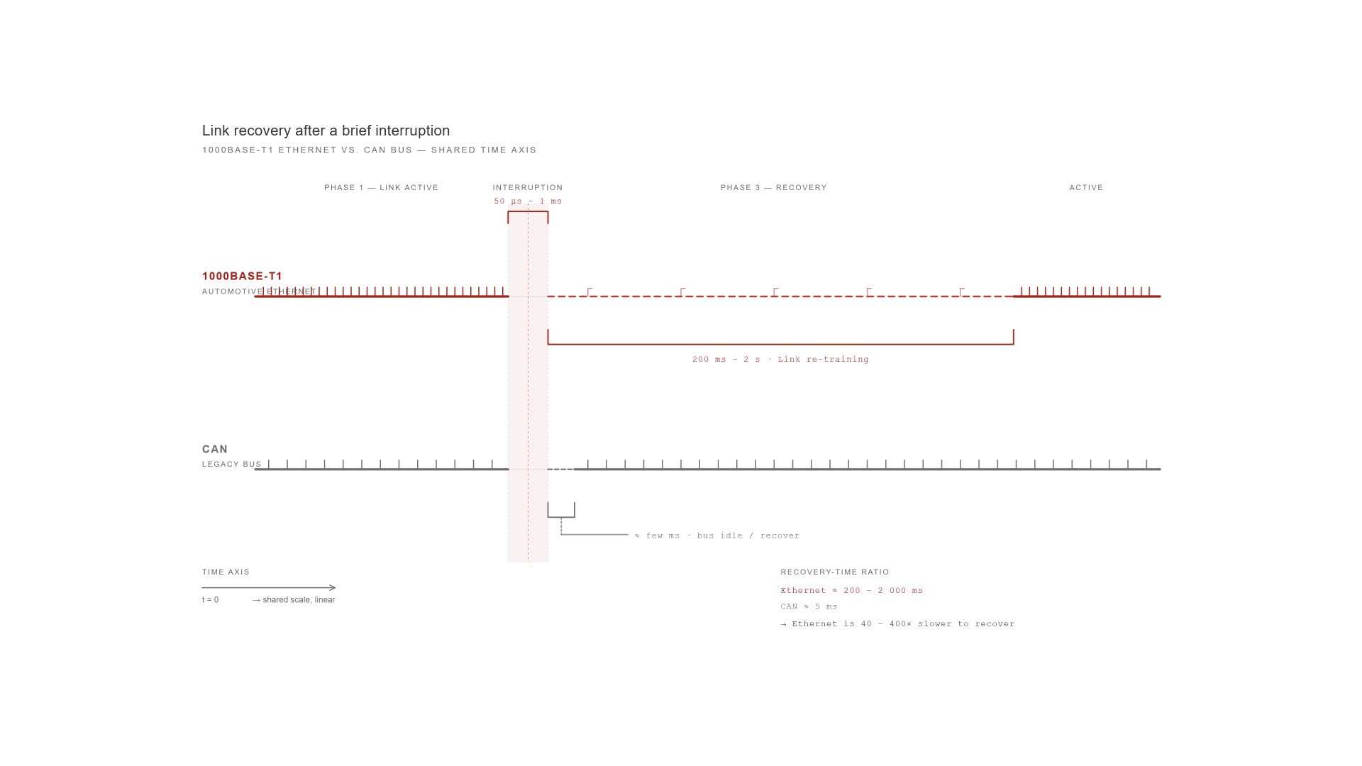
These recovery times are what LV124 / LV148 short interruption tests are designed to measure. The norm defines the interruption duration, the number of repetitions, and the acceptance criteria for whether the ECU passed or failed.
Why standard test equipment cannot handle this
Here is the core problem: most LV124 / LV148 test setups were designed for power line interruptions and CAN/LIN bus switching. They use electromechanical relays or basic semiconductor switches that work well at low frequencies — but cannot cleanly interrupt a 1 Gbit/s signal without introducing artefacts.
Signal integrity during switching
A 1000base-T1 signal uses PAM-3 encoding on a single twisted pair at 750 MHz symbol rate. Opening and closing a relay in the signal path introduces impedance mismatches, reflections, and ringing that can corrupt the link state — making it impossible to distinguish between an intentional test interruption and a signal integrity failure.
Switching speed requirements
LV124 requires interruptions as short as 50 microseconds. At 1 Gbit/s, 50 microseconds is 50,000 bits — enough time for the PHY to detect a link failure. The switching device must open and close cleanly within this window, with defined transition edges and no bounce.
Simultaneous power and data interruption
The norm requires testing what happens when both the power supply and the communication line are interrupted simultaneously — or in defined sequences. This means the interruption device must coordinate power line and Ethernet line switching with precise timing, synchronised to the test controller.
Monitoring during the test
During the interruption test, the test system must monitor whether the Ethernet link actually dropped and when it recovered — requiring a separate monitoring path that does not interfere with the test. Standard test setups have no way to observe the Ethernet physical layer state during an interruption.
The WKS UFI — built specifically for this problem
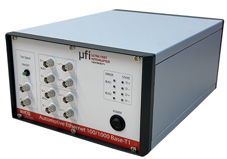
The Ultra-fast Interrupter (UFI) from WKS Informatik was designed from the ground up to handle interruption testing on high-speed serial interfaces — not as an afterthought, but as a core capability.
WKS Ultra-fast Interrupter (UFI)
Worldwide first to support Automotive Ethernet 1000base-T1 and GMSL interruption testing
The UFI performs LV124 / LV148 short interruption tests on power lines and high-speed communication lines simultaneously — with the switching precision and signal integrity required for gigabit-speed interfaces.
Power lines: Up to 125A
Standard buses: 4 × CAN, LIN
Ethernet: 100base-T1 & 1000base-T1
GMSL: Full support
10G Ethernet / GMSL2: New generation UFI (2026)
Integration: Standalone or in RTStand LV124 / LV148
The UFI handles the signal integrity challenge by using purpose-designed high-frequency switching paths for each interface type — the Ethernet switching path is not the same circuit as the power switching path. This ensures clean interruptions without impedance artefacts, reflections, or crosstalk.
Within the RTStand system, the UFI is fully automated — interruption profiles, timing sequences, and coordination with power supply tests are all controlled by the RTStand software framework. No manual intervention is required between tests, and all interruption events are logged and time-synchronised with the voltage, current, and bus communication data captured by the Tube Analyzer.
10G Ethernet and GMSL2 — what comes next
The interface evolution is not slowing down. 10G Ethernet (10Gbase-T1) is already in development for next-generation vehicle architectures — supporting zonal controllers that aggregate data from dozens of sensors and cameras. GMSL2 and GMSL3 push camera link bandwidth to 6–12 Gbit/s, supporting higher-resolution sensors and multi-camera arrays.
WKS Informatik is actively developing UFI hardware for these next-generation interfaces. The new generation UFI — announced in 2026 — adds support for 10G Ethernet and GMSL2 interruption testing, ensuring that the RTStand platform remains current as vehicle architectures evolve.
Future-proofing
If your current ECU development project targets interfaces that will ship in vehicles 3–5 years from now, your test infrastructure needs to support those interfaces today. WKS builds RTStand and the UFI with exactly this lifecycle in mind — continuous hardware and software updates ensure your system stays relevant for the duration of your product’s life.
For the complete picture of how RTStand handles all nine LV124 / LV148 test types — including how Ethernet and GMSL interruption tests fit into the overall automated workflow — see: What is LV124 / LV148? The complete guide.
Need to test Automotive Ethernet or GMSL under LV124?
Talk to us about your ECU’s interface requirements. We can run a proof-of-concept test in our lab with your DUT — or spec the right UFI configuration for your in-house setup.
RTStand LV124 / LV148
Built by WKS Informatik GmbH · Ravensburg, Germany – Imprint